
Table of Contents
ToggleInstalling a garbage disposal isn’t rocket science, but it’s not a slap-it-together job either. One wrong connection and you’re dealing with leaks, electrical faults, or a disposal that grinds for three seconds before tripping the breaker. A detailed installation diagram cuts through the guesswork, showing exactly where each wire connects, how the drain assembly fits together, and where that dishwasher drain hose actually goes. Whether you’re replacing a worn-out unit or adding a disposal for the first time, understanding the layout, from the mounting assembly to the electrical junction box, makes the difference between a smooth install and a callback to a plumber.
Key Takeaways
- A garbage disposal installation diagram shows four critical zones—mounting assembly, grinding chamber, drain connections, and electrical supply—eliminating guesswork and preventing costly mistakes like leaks or electrical faults.
- Always shut off power at the breaker and use a non-contact voltage tester before making any electrical connections; match wire colors (black to black, white to white, ground to ground) and ensure a dedicated 120-volt circuit with GFCI protection per NEC guidelines.
- Removing the dishwasher knockout plug before final assembly is essential; failure to remove it is the #1 installation mistake that prevents proper drainage and forces unnecessary troubleshooting.
- Use plumber’s putty (not silicone) for the sink flange seal, assemble the mounting ring evenly in a star pattern, and test all joints for leaks with water before declaring the installation complete.
- The dishwasher drain hose must form a high loop secured to the underside of the countertop before entering the disposal to prevent backflow and comply with plumbing codes.
- Hand-tighten discharge tube slip-nut fittings, then give them a quarter-turn with groove-joint pliers—overtightening cracks plastic threads and using Teflon tape on compression fittings causes leaks rather than prevents them.
Understanding the Essential Components in Your Garbage Disposal Diagram
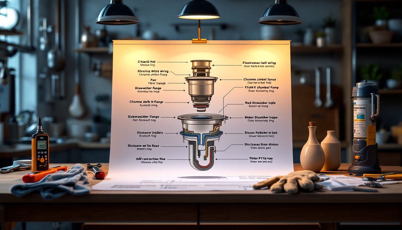
A kitchen sink garbage disposal installation diagram breaks down into four main zones: the mounting assembly, the grinding chamber, the drain connections, and the electrical supply. Each plays a critical role, and misunderstanding even one can derail the whole project.
The mounting assembly typically uses a three-bolt or EZ-mount system. The sink flange sits flush with the sink drain opening, sealed with plumber’s putty. Below that, the fiber gasket, backup flange, and mounting ring clamp onto the sink from underneath. The disposal body then twists or clips into this ring, no screws needed once it’s seated.
The grinding chamber houses the impellers (not blades, they’re blunt lugs that pulverize food against a stationary grind ring). The motor sits below, usually ½ to 1 horsepower for residential units. Most diagrams label the reset button on the bottom and the hex-socket wrench port for clearing jams.
On the drain side, you’ll see the discharge tube extending from the side of the disposal. This connects to the P-trap via a slip-joint fitting. If you have a dishwasher, the diagram will show a dishwasher inlet near the top of the disposal body, a nipple typically plugged with a knockout cap that must be removed before hooking up the dishwasher drain line.
The electrical junction varies by model. Hardwired units have a cable entering through a strain relief connector on the bottom or side. Plug-in models use a grounded three-prong cord that connects internally. Most diagrams clearly mark the hot (black), neutral (white), and ground (green or bare copper) wire terminals inside the access plate.
Step-by-Step Installation Process Using a Wiring Diagram
Follow the visual layout to avoid backtracking or, worse, reinstalling the entire unit after realizing you forgot the dishwasher knockout.
Electrical Connections and Safety Requirements
Before touching any wires, shut off power at the breaker, not just the wall switch. Use a non-contact voltage tester to confirm the circuit is dead. Most garbage disposals draw 5–8 amps and require a dedicated 120-volt, 15 or 20-amp circuit with GFCI protection per NEC guidelines, though local codes vary.
Remove the electrical access plate on the bottom of the disposal (usually one screw). If using a power cord, thread it through the strain relief fitting and tighten the clamp before making connections. Match wire colors: black to black (hot), white to white (neutral), and green or bare copper to the ground screw on the disposal’s metal housing. Twist connections clockwise with wire nuts, tug-test each one, then fold the wires neatly back into the compartment and replace the cover plate.
Hardwired installations follow the same color code but pull power from a junction box under the sink or in the basement. Use 12/2 or 14/2 NM cable (depending on amperage) and install a wall switch above the counter to control the disposal. Label it clearly so no one confuses it with the light switch.
Wear safety glasses and gloves during all electrical work. Water and electricity are a bad mix, so double-check that all wire nuts are tight and no bare copper is exposed.
Plumbing Connections: Drain Lines and Dishwasher Integration
Start by assembling the sink flange. Roll a ½-inch rope of plumber’s putty and press it around the underside of the flange lip. Insert the flange into the sink drain hole from above, pressing firmly. From below, slide on the fiber gasket, backup flange, and mounting ring, then tighten the three mounting screws evenly in a star pattern until the flange is snug and excess putty squeezes out. Wipe away the excess with a rag.
Lift the disposal into position (they typically weigh 10–15 pounds, so use both hands or get a helper). Align the mounting tabs and twist or clip the unit into the mounting ring until it locks. Some installers use a short section of 2×4 or a bucket to support the weight while securing it.
If integrating a dishwasher, locate the knockout plug inside the dishwasher inlet on the disposal. Use a screwdriver and hammer to punch it inward, then retrieve it from inside the grinding chamber with needle-nose pliers, leaving it in will clog the disposal immediately. Attach the dishwasher drain hose (usually ⅝-inch rubber tubing) with a hose clamp. The hose must loop up and secure to the underside of the countertop or sink deck before descending into the disposal to prevent backflow: this is called a high loop and is required by most plumbing codes.
Connect the discharge tube to the P-trap. Most disposals include a rubber gasket and slip-nut fitting. Measure and cut the discharge tube or elbow if needed with a hacksaw, PVC cuts clean at 90 degrees. Hand-tighten the slip nuts first, then give them a quarter-turn with groove-joint pliers. Don’t overtighten or you’ll crack the plastic threads.
Run water and check for leaks at every joint: sink flange, discharge tube, dishwasher hose, and P-trap. Tighten as needed. Many pros keep the cabinet dry for 24 hours and recheck before calling it done.
Common Installation Mistakes to Avoid
The knockout plug is the #1 culprit. Forgetting to remove it means the dishwasher won’t drain, and you’ll think the disposal is defective. Always fish it out before final assembly.
Using Teflon tape on slip-joint fittings is unnecessary and can cause leaks, those connections rely on compression and rubber gaskets, not thread sealant. Save the Teflon tape for threaded metal fittings.
Skimping on the plumber’s putty or using silicone instead can lead to slow leaks around the sink flange. Putty stays pliable and won’t harden over time like some silicones. If your sink is acrylic or composite, check the manufacturer’s guidance, some materials react to petroleum-based putty.
Reversing the hot and neutral wires won’t necessarily stop the disposal from running, but it’s a code violation and a safety risk. Always follow the diagram showing wire placement in the unit’s manual.
Overtightening mounting bolts can crack the sink or the disposal flange. Snug is enough, you’re compressing a gasket, not crushing metal.
Forgetting to reset the unit after installation is surprisingly common. Most disposals ship with the reset button (usually red) popped out on the bottom. Press it in before testing.
Tools and Materials You’ll Need for Installation
Gather everything before you crawl under the sink. Stopping mid-job to hunt for a wrench wastes time and tests patience.
Tools:
- Screwdrivers (flathead and Phillips)
- Adjustable wrench or slip-joint pliers
- Hacksaw (for trimming discharge tubes)
- Wire strippers and wire nuts (if hardwiring)
- Non-contact voltage tester
- Hammer (for knockout plug removal)
- Hex wrench (usually included with disposal for jam clearing)
- Plumber’s putty or putty knife
- Safety glasses and work gloves
- Flashlight or headlamp
Materials:
- Garbage disposal unit (½ to 1 HP, depending on household size)
- Power cord (if not hardwiring)
- Dishwasher drain hose and clamps (if applicable)
- PVC discharge elbow and tailpiece extensions (measure your setup, some kits include these)
- Plumber’s putty
- Wire nuts (usually included, but have extras)
- Teflon tape (only for threaded metal fittings, not slip joints)
- Electrical tape (for securing wire nut connections)
Many DIY project tutorials recommend having a bucket and rags handy to catch residual water from the drain lines. Even if you’ve removed the P-trap, there’s always a tablespoon or two lurking.
Conclusion
A clear garbage disposal installation diagram removes the mystery from what looks like a tangled mess of pipes and wires. Follow the layout, respect the electrical codes, and don’t skip the dishwasher knockout if you’ve got one. Measure twice, tighten once, and test everything before you call it done. With the right diagram and a methodical approach, this is a half-day project that saves a few hundred dollars in labor, and gives you a disposal that runs quietly and drains cleanly for years.